Design Process of Fuel Injector Intake Manifold and Fuel Rail
When Fuel if flowing in injector, it pushes injector in
to intake manifold hole or this force will compress cushion. Additionally
Crushing of Injector due to wrong injector installation height (48.66mm as
shown)- if tolerance stack up analysis is wrong then injector cushion and
O ring will be damaged and this will leads to fuel leakage.
O ring selection for leakage prevention –
Following 2 parameters are
calculated for leakage prevention.
Ø Compression Ratio = Change
in O ring Dia/free O ring Dia= (D-t)/D =3.5-2.9/3.5=18 %
Ø 


 Filling Ratio =O ring area /groove area=[π * (D/2)^2 ]/
[b*t]= [3.14*(3.5/2)^2]/[4*2.9]=82%
Injector sitting whole dimension have
fixed reference:
1. Fix
mounting hole of Rail on Intake Manifold for dimension measurement
2. Fix
Intake Manifold mounting hole on Cylinder Head for dimension measurement
|
Manifold Design
|
Spec mm
|
Remark
|
|
Injector O Ring D / d
|
15.2 / 3.5
|
Used for Intake Grove Design
|
|
Injector sitting area
tolerance
|
+/-0.1
|
On surface b, z, d4 surface
|
|
Injector sitting
surface finish
|
Ra 6.3
|
On surface b, z,a,d4 surface
|
|
Chamfer Angle (α)
|
25 ° +/- 1
|
To avoid cutting of O Ring
|
|
Chamfer Height z
|
2 + 0.5/ -0
|
|
|
Stopper Surface for
Injector
|
7 +/- 0.23
|
Injector O Ring cannot slide in to intake hole
|
Generally 4-5 bar ia pressure in gasoline fuel system and when high pressure fuel if flowing in injector, it pushes injector in to intake manifold hole or this force will compress cushion. Now due to this fuel pressure injector press the cushion fitted in intake manifold groove. To prevent this many fuel injector has clip - in next article we will learn how to design clip for fuel injector.
Ø Compression Ratio = Change
in O ring Dia/free O ring Dia= (D-t)/D =3.5-2.9/3.5=18 %
Ø 


 Filling Ratio =O ring area /groove area=[π * (D/2)^2 ]/
[b*t]= [3.14*(3.5/2)^2]/[4*2.9]=82%
For background, please read previous blog and for further design process read next blog.
Next topic is related to wall wetting and tolerances
Intake
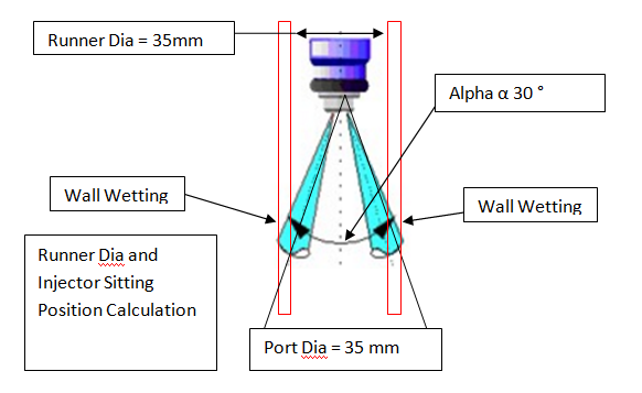
Runner Wall and Valve Wetting –
Fuel can go on runner wall or Valve stem; for better
mixing of air and fuel spray angle of injector is optimized. In case of single
port and two intakes valve if injector physically rotate this may leads to
valve wetting.


