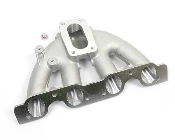
Fuel Rail Assembly Design on Intake Manifold
Fuel Delivery Pipe/Rail is mounted on Intake Manifold - Design Process
Stack up Analysis of Tolerance is very crucial to design Rail Mounting. As
shown in below figure Fuel injector is placed between fuel delivery rail and
intake manifold injector sitting groove. Installation height is perpendicular
distance between injector mounting surfaces. Installation height with tolerance
must be equal to length of injectors with tolerance. To insure surface finish
area and depth on intake manifold following to calculation must be done:
1. Max
distance between upper and lower O Rings of injector < Minimum Gap between
(O Ring Position in Rail) and (O Ring Position in Intake Manifold)
if point 1 is not satisfied then fuel will leak from contact point of two parts - either from (injector and intake) or from ( Injector and Rail).
2. Minimum
distance between upper and lower O Rings of injector > Maximum Gap between
(O Ring Position in Rail) and (O Ring Position in Intake Manifold)
Injector O Ring will be crushed if this point 2 condition is not met.
Step 1 was Requirement Study
Step 2 was DFMEA of Intake Manifold
Step 3- Assembly of Fuel Injector on Intake Manifold plus Assembly of Fuel Delivery Rail on Intake Manifold
Step 4 - Calculate axis of fuel injector , Axis of cup in Intake Mani and Cup in Fuel Rail. - For Next Step Read next article Co-axiality and Concentricity.
Co-axiality and Concentricity:
Intake Manifold
Injector Sitting Hole must be co-axial to Rail Hole; but as rail itself is
mounted on intake manifold, geometric tolerances with maximum material
condition must be used to define location of rail mounting hole with respect of
Injector Hole in Intake Manifold.


