Intake Manifold Stress Analysis and Performance Test
To start 3D design - benchmark with various designs used in past for shape and size. Because 1 D simulation in GT, Ricardo, Lotus etc give spec and not shape. Check previous blogs to understanding modeling in 1D. As it is design phase, we will make proto part only - i.e only few intake manifold will be made so ADC12 is best. Plastic moulding machine is very costly so amortization is not possible for prototype part. On these few component physical part level testing will be done as explained in end of this blog. After successfully completing these physical tests, further optimization in intake manifold design will be done.
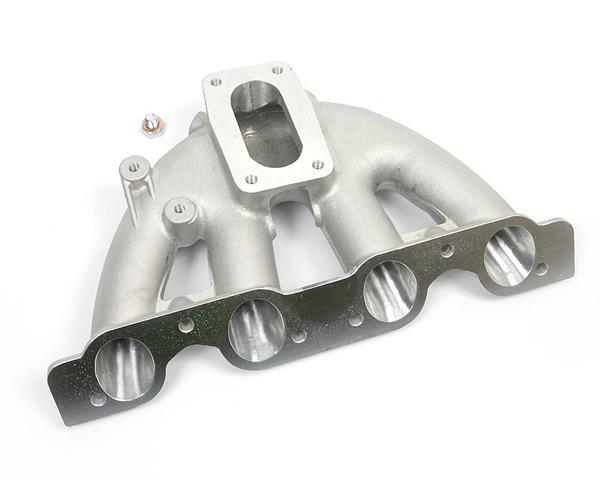
In-Manifold 3D was made in solid work considering 2.8 Liter Volume and 260 mm runner length with 35 mm circular Dia. This is basic primary shape to start 3D Analysis.
In-Manifold 3D was made in solid work considering 2.8 Liter Volume and 260 mm runner length with 35 mm circular Dia. This is basic primary shape to start 3D Analysis.

Strength
Simulation:-
For
above made CAD 3D, ADC 12 properties used for strength analysis. Meshing
parameters are shown in table. ADC12 is best because we can make it by sand casting which is very low cost. After sand casting machining will be done to achieve surface finish, GDNT and roughness etc. Plastic or PA66GF35 can be used but plastic moulding machine machine is very costly.
Mesh
type
|
Solid
Mesh
|
Mesher
Used:
|
Standard
mesh
|
Jacobian
points
|
4
Points
|
Element
Size
|
10.3939
mm
|
Tolerance
|
0.519694
mm
|
Mesh
Quality
|
High
|

Conclusion
from above Graph:-
To reduce weight runner thickness can be
reduced as stress is less in runner. To reduce stress on diffuser mounting
place, thickness of this surface will be increased.
Intake Manifold Part Level Testing
Performance Test for Intake Manifold
1-Air Tightness of Plenum and Runner
Plug All
Runners and Injector Hole. Apply -20 Bar Vacuum from Air Inlet Hole
Maximum
Pressure Drop 0.6 KPa. Compare before and after test part dimension.
2-Injector Sitting Area Test
Assembly
Rail and Injector On In-Mani. Apply 30 Bar Pressure from Rail.
No Fuel
Leakage should occur from both O side of Injector.
3-Vibration Test
Fix
In-Mani on Fixture. Apply 30g Vibration in X,Y and Z direction for 500 Hours.
Do Test
Number 1 and 2.
4-Thermal Test
Keep
Intake Manifold at 200 °C for 500 Hour.
Do Test
Number 1 and 2.
5- Engine Level Test and Vehicle Level Test
Vehicle
Calibration, Engine Calibration, Engine Durability and Vehicle Durability
After
Test, dismantle intake and do Test Number 1 and 2.
Please check previous articles for Intake Manifold Layout, DFMEA, Plenum Volume, Runner Length and Cross Section, 1 D Simulation analysis from scratch and also Intake Noise Study, Resonator retirement study, Positioning on MAP Sensor on Intake Manifold etc.