How Formula Student FSAE can write Result and Discussion, Conclusion and Further Study
It is an example only, please read previous blogs for details.
Result
and Discussion (Group)
Vehicle System was divided in to 4
gropes: Powertrain, Chassis, Suspension and Driver Control. Design of
Powertrain was further divided into 3 sections; Engine, Auxiliary and
Transmission. My work is related to Main engine, intake and exhaust system
optimization. In below table requirement from different group is explained;
these requirements were generated from powertrain team members, MSc Vehicle
Level Group members and FASE Approval Judges. As physical calibration, durability
and performance testing is not finished yet, there will many more interrelated
performance points such as vehicle acceleration, noise vibration. For these Group–requirements team meeting were
organized and accordingly agreement were taken; these Group requirement with
Agreement is discussed in below table; also scheme / effort estimated from my
side is given in below table.
|
Group – Requirement
|
Result Achieved / Agreement
|
Scheme / Effort
|
|
Transmission – Keep Torque High
|
Engine : Max Torque 57 Nm@11000RPM
|
After each iteration results were shared with
Transmission. After optimizing whole Intake and Exhaust parts this
performance was achieved.
|
|
Transmission – Keep Torque Smooth
|
Pros: 9000-12000RPM torque is almost constant 55 Nm. Cons: Between 5000 to 7000 RPM
Torque decrease from 40Nm to 35 Nm then rise to 45Nm.
|
To keep torque smooth, Sharp Peak Torque (70Nm at
11000RPM) deign was rejected. Smaller but more smooth torque design was
selected (57Nm at 11,000RPM)
|
|
Transmission – Zooming requirement
|
From 1000 to 4000 RPM Output Torque become 0 to
40 Nm
|
By further optimizing Intake Silencer This can be
improved as mentioned in report.
|
|
Cooling System – Provide Total Heat Generated
|
A Graph was provided to Cooling System for Intake
Air Mass Flow Rate. (such as 0.02 Kg/ sec at 11000 RPM)
|
By Multiplying Air Mass Flow Rate and Caloric
Value Cooling Team can calculate Total Heat Generated.
|
|
Fuel System
- Provide Injector Sitting
Space on Intake Manifold
|
Intake Manifold Injector O Ring Compression
18% and Filling Ratio 82% is as per
standard
|
In Intake Manifold hole is designed for Injector
Sitting and Leakage Presentation.
|
|
Fuel System
- Provide Fuel Delivery Rail mounting on Intake Manifold
|
Two M6 Bolt Blind Hole (with Tolerance +/-0.05 mm
in X, Y and Z with respect to Injector Hole) will be provided for Rail.
|
Injector Installation Height, Co-axiality,
Concentricity, Injector Spray Angle, Runner Dia etc have been explained in
report.
|
|
Fuel System , Cooling & Lubrication System –
Component Safe Assembly on Engine
|
Engine Envelop is considered with 5 ° with 10 mm
movement in X, Y & Z direction so that enough free space can be provided
for nearby parts such as Fuel Hose, Oil Pump,
|
Exhaust System is kept far away with Heat Shield
Cover. Engine Envelope is kept bigger for safe design.
|
|
Driver Control -
Wiring Harness and Connector
|
CAD data is made for all sensor location so that
Driver Control can measure length of required wire. Also Connector and wire
requirement is discussed with Driver Control Team.
|
Weekly Team Meeting for agreement on Sensor
Design, supplier and location on engine. (Sensor – Knock Sensor, Temperature
Sensor, MAP Sensor, TPS sensor, CAM sensor etc)
|
|
Driver Control – Sensors (Inlet Air Temperature Pressure , Mass
Flow, Oxygen etc)
|
Temperature Sensor – On Air Cleaner Pressure Sensor – On Plenum Mass Flow Sensor –
After Restrictor on Intake Manifold; Oxygen Sensor – M10 Screw Hole is
provided at two places before and after Catalyst in Exhaust Manifold
|
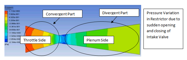
Hole on Air Cleaner is provided for Temperature
Sensor mounting. CFD and guidelines is mentioned for Pleasure Sensor Location
Freezing on Plenum. Also to avoid Electromagnetic Noise all sensor wires must
be shielded twisted pair or always from high voltage wires of Spark plug,
Starter Motor etc
|
|
Driver Control – Electronic Throttle Body &
TPS
|
Throttle Body Bore, Shat Dia, WOT, Full Close is
fixed. 6 Pin Bosch Throttle will be used; 2 Pin for Motor, 3 Pin for Two TPS,
1 For common Ground.
|
As per FSAE rules, DFMEA for Electronic Throttle
is mentioned in report.
|
|
Driver Control – Accelerator Pedal Design Change
|
Agreement to use Electronic Sensor in Accelerator
Pedal as Electronic Throttle will be used.
|
Team Meeting for agreement from Chassis for
Accelerator Pedal Mounting on Body Panel
|
|
Dyno – Map
Sensor Performance Verification
|
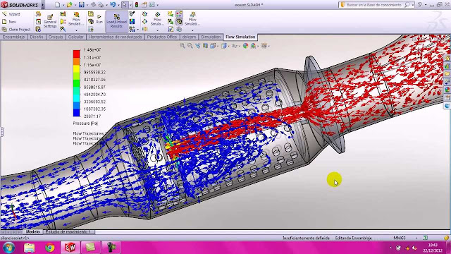
Air Flow Simulation result shared with Dyno
Testing Group for Verification. Sensor is placed away from runner and
Restrictor; where Air velocity is almost constant in plenum.
|
A highly accurate and sensitive sensor-1 will be
placed in place of Bosch MAP sensor. Pressure Reading from Sensor-1 and Bosch
Sensor will be compared for location fixing on Plenum Body.
|
|
Dyno – Temperature
Sensor Verification
|
0 to 5V, Range -40 °C to 200 °C, Accuracy +/- 0.5
°C
|
Two-Wire Thermocouple type sensors fitted in Air
Cleaner. (i.e. before Throttle)
|
|
Dyno – Throttle Fail Safe Mode Setting
|
Aluminum stopper is given in Casting of Throttle
Body so if Valve/shaft/spring or electrical failure occur vehicle speed will
become 30 Km/h. Stopper will keep valve angle 12° in case of sudden failure.
|
If throttle body fail and vehicle is moving at
very high speed; the vehicle speed should not become 0 as other chasing
vehicle can hit from behind and cause severe accident.
|
|
Dyno – Throttle and Vehicle Idle Speed Control
|
Idle Engine Speed = 1000 RPM.
|
Throttle Full Close Angle is set 5 °. Aluminum
stopper is given in casting to maintain this angle.
|
|
Dyno – Throttle and Vehicle Speed Fluctuation
|
Throttle Motor Angle Resolution = +/- 0.06 ° Maximum; 0.06 differ in
angle leads to differ Inlet Air Volume and fluctuate engine RPM by +/-
25.
|
More than +/- 25 RPM variation will lead to drivability
problem as vehicle speed variation will became substantial.
|
|
Vehicle Stability
|
Engine is located near rear wheel and Engine
height of centre of gravity is kept low.
|
This design will help in Braking and Steering
Control. ( Front Weight Transfer and Cornering Side Weight Transfer)
|
|
Chassis Frame Strength
|
Three Point Hydraulic Mounting used for Engine
Mounting. Aluminum, Plastic, Steel
Alloy will be used to keep engine weight low.
|
Hydraulic
Mounting and Lower weight of engine
|
|
Noise Approval: Sound Level
|
Physical Test Require to confirm this; As by
simulation on Torque Fluctuation due to silencer can be checked.
|
Proper Mounting and Assembly location on Chassis
design for Intake and Exhaust Silencer.
|
|
Safety - Firing Frequency Resonance and Chassis
Strength
|
First Order Engine Firing Frequency = (Max
RPM/60) X (Number Of Cylinders / 2*) = (16000/60)X(4/2) = 533.3 (* For Four Stroke)
|
Natural Frequency of Each Intake and Exhaust
Component is kept above (533.3) Engine RPM frequency. There will not be
resonance between Engine Vibration and individual component.
|
|
FSAE Approval
|
Tail Pipe End is kept just 40 Cm behind Rear axle
and 20Cm above ground.
|
Engine height of centre of gravity is kept low;
Inclined tail pipe is used to accommodate length of Tail Pipe.
|
|
FSAE Approval
|
All part positioned under defined boundary such
as air filter, intake duct and exhaust tail pipe. Cover Intake System parts
if below 350mm height.
|
Chassis Frame design has mounting and bolting
position as per Intake system component requirement.
|
|
FSAE Approval
|
Calibration, safety and driver control related
rule has been followed while buying Throttle. Bosch can meet all specified
FSAE regulation and Motec ECU can do matching with it.
|
Two separate TPS (both reading within 10%), Cover
is provided on Throttle to prevent oil, grease etc, Two return springs
provided to throttle shaft for safe return.
|
Conclusion:
This
report of Engine Design has broadly and critically evaluated both the aspects:
1st Managerial and 2nd Technical for designing Intake and
Exhaust System for FSAE race vehicle. The 1st Part Managerial
analysis for Engine development has been presented considering internal and
external environment using PEST, SWOT, Financial Investment, Human Resource
Requirement, Location, Responsibility Division and Scheduling. 2nd
Part Conventional Technical steps such as Design, Testing, Quality and
Procurement have been explained in detail using standard tools of costing,
scheduling and controlling process. Techno-commercial Management issues such as
Value Analysis/Value Engineering, Cost Control, Risk Management etc has been
identified and countermeasure to each possible failure has been presented in
Management report. Race Day technical, environmental, ecological, social and
managerial issues have been considered while designing each component. Certainly
Engine Design report is very inclusive and investigative; It is agreed with MSc
group to consider this proposal for financial go ahead as soon as possible so
that further steps can be taken to meet FSAE 2016. Addition to FSAE participation,
there is an element of design experience and technical learning by this project;
following list comprises design experience and leaning achieved by this
project.
|
Component
|
Design
Experience
|
Technical
Learning
|
|
Electronic
Throttle
|
45mm Bore, Full Close
Angle 5, WOT 85, Two TPS 0 to 5V, 10mm Shaft Dia, Aluminum Body with Steel
Valve, DC three phase motor.
|
Fail Safe Mode, Bore Dia Optimization, CAD Data making
|
|
Diffuser Restrictor
|
Length 250mm from
45mm to 20mm, Length 250mm from 20mm to 60mm, Steel Body
|
CFD for air flow
|
|
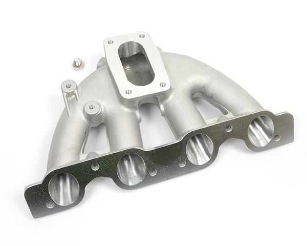
Plenum
|
2.8 Liter, Restrictor
Inlet at Centre of plenum i.e. equidistance from all runners, Aluminum Sand
Casting with Machining
|
Plenum Noise Optimization, CAD Data Making and Strength Simulation
|
|
Runner
|
Length 260mm , Dia
35mm Throughout, Aluminum Sand Casting
|
Method to achieve High Constant Torque, Tolerance Analysis for
Injector
|
|
Exhaust Manifold
|
Pipe Length 240mm,
Dia 38mm Throughout, Cata Volume Space 2.25 Liter, Exit Area 2100 mm2
|
Back Pressure impact on Volumetric Efficiency
|
|
Muffler
|
Simple Perforated Type, Inlet Pipe L 250mm , out let pipe 59mm, Inlet
Dia 75mm, Out Let Dia 75mm
|
Effect of Muffler shape on Torque output
|
|
Engine
|
57Nm @ 10,000 RPM (9000 to 12000 Constant Torque)
|
Engine Simulation
|
Further Study:
Previous batch has worked
on Intake and Exhaust System Design. Similarly our focus was on improvement in previous
year engine performance by improving previous intake and exhaust system designs
so that we can get approval to participate in FSAE Race however we have not
focused on advanced technology. Further study should not be done in improving
our proposed designs or FSAE approval related technology but further study must
focus on new technology. Further study
must be done in following areas; these are new technology in Electronic Fuel
Injection system so that it can meet FSAE regulation also.
|
Component Function
|
Parameters
|
|
Variable
Intake Runner
|
Length
and Dia of each runner will be different for different cylinder. As a result
engine cylinder will give equal power and torque. It also helps in balancing
of engine so noise and vibration reduce.
|
|
Open
Valve Injection with Long Reach Injection
with Dual Injector per Cylinder
|
To
negate injection delay, long nozzle length injector is being used for
Electronic Port Injection System. This can be tried for our Engine also with
small modification in Intake Manifold design and Injection Mapping.
|
|
As
Gasoline Direct Injector is not permitted; Open Valve Liquid Fuel Injection
just when intake valve are open; it’s like gasoline direct injection in
combustion process. If GDI can give
constant torque and increase torque by 15-20%; Similarly Open Valve Injection
can give 5 % improvement in torque. Additionally NOx reduce by Fuel cooling
of Combustion chamber.
|
|
|
Electronic
Throttle Torque Based Mapping
|
Torque
Based Mapping can be done only with Electronic Throttle; It has correction
factor to make keep torque constant by changing amount of fuel injected and
opening throttle accordingly.
|
|
Intake
Silencer Improvement
|
There
is further scope in Intake Noise reduction. Current Design is not very
satisfactory.
|
|
Muffler
Design Improvement
|
There
is further scope in Intake Noise reduction. In current system there is abrupt
torque variation.
|
|
Single
Cylinder 600 cc Engine
|
As
per our benchmarking result; Further study can be done to use single cylinder
Engine from KTM. As single cylinder mass is very less, it can improvement
vehicle performance.
|
|
Knock
Improvement
|
Single
knock sensor per cylinder for better measurement of knocking. This will
improve in between fueling and vibration control. This ll ultimately improve
vehicle drivability and
|
|
Use
Integrated Temperature and Pressure Sensor and Mass Flow Sensor at two places.
|
By
measuring temperature and pressure near air cleaner and then near runner,
correction factor can be calculated for correcting amount of fuel required.
This will leads to improvement in fuel efficiency.
|
|
EGR
(Exhaust Gas Recirculation)
|
FSAE
allow waste heat usage by 100%. EGR must be design to improve torque output,
for intake air mixing and cooling at high speed air cooling can be used. For
low speed intercooler will be required which can lead to cost up. So EGR
valve can be calibrated to switch on when speed is above 80Km /hour - inlet
change cooling simulation required to confirm vehicle speed.
|