Silencer Muffler Design, Material, Flow Simulation, Baffle Plate, Back Pressure, Simple Perforated Muffler Silencer
Please read previous blog for exhaust system design management and silencer muffler requirement.
The design process of the exhaust
muffler should comprise a precise approximation of space essential for the
exhaust component, backpressure to engine, components weight, gas flow and
distributions, gas density and temperature distributions, the interaction of
the plenum with external surfaces around, and the thermal interaction of the
exhaust muffler with external surfaces through internal convection, conduction,
and radiation. CFD investigations of exhaust mufflers should take much
iteration time to converge, and study should not exclude complicated models
because the flow regimes comprise high subsonic compressible internal flow,
regions with high vortices and low velocity wake regions.
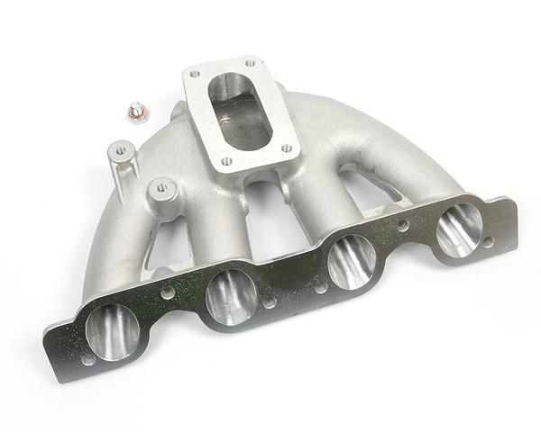
Exhaust manifold should be considered
for reducing the angle of bend pipes all through the exhaust gases path to
decrease the air friction. For initial study, few assumptions needs to be
considered such as flow of burning gases at a speed of 20 m/s and a temperature
of 300°C. The Flow and Pressure simulation should be done to study volumetric
efficiency and back pressure.
In above model exhaust silencer will be
added now. Assumption has been taken for end correction values as shown below:
From above graph it can be concluded that ES12-SP simple
perforated type muffler should be used; Similar to below shown muffler can be
purchased from supplier. First step to check with Yamaha if they have similar
specification muffler as we will use Yamaha engine.
Individual
Pipe, From Exhaust Port to Exhaust Manifold: - Dia 40mm and Length 250 mm
Exhaust
manifold Volume: -
2.5 Liter
Pipe,
From Manifold to Muffler: -
Dia 75 mm and Length 250 mm
Pipe,
From Muffler to atmosphere: - Dia 75 mm and length 50 mm


