Fuel Injector O Ring Design and Wall Wetting on Intake Manifold
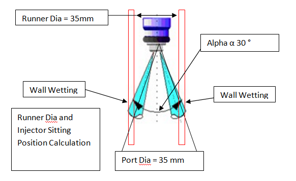
Injector Rotation can increase wall wetting as injector is mostly double jet now as two intake ports per cylinder is common. Angle between these cones (Alpha) and cone angle (Beta) must be taken in to account while deciding distance of injector sitting plane from runner end (port side). Injector also has third angle Gamma for perpendicular to injector z axis plane; this is angle perpendicular to both injector axis and spray plan.
O ring selection for leakage prevention –
Following 2 parameters are
calculated for leakage prevention.
Ø Compression Ratio = Change
in O ring Dia/free O ring Dia= (D-t)/D =3.5-2.9/3.5=18 %
Ø 


 Filling Ratio =O ring area /groove area=[π * (D/2)^2 ]/
[b*t]= [3.14*(3.5/2)^2]/[4*2.9]=82%
Specification
|
Standard (Criteria)
|
Our Design
|
Conclusion
|
O Ring Compressibility
|
Must be between 12 to 25%
|
18 %
|
In-Mani Grove Dia (d4=14) is Safe Design
|
O Ring Filling Ratio
|
Must be between 70 to 85%
|
82%
|
Intake
Runner Wall and Valve Wetting –
Fuel can go on runner wall or Valve stem; for better mixing of air and fuel spray angle of injector is optimized. In case of single port and two intakes valve if injector physically rotate this may leads to valve wetting
Injector Rotation can
increase this wall wetting as injector is double jet. Angle between these cones
(Alpha) and cone angle (Beta) must be taken in to account while deciding
distance of injector sitting plane from runner end (port side). Injector also
has third angle Gamma for perpendicular to injector plane; this is angle
between injector axis and spray axis.


