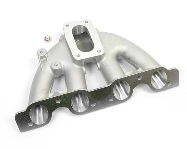
Exhaust Manifold and Silencer Muffler Design Management Process
Please read previous 2 blogs for Exhaust System Design Process, Design Review and DFMEA.
Please read intake manifold and throttle system design blogs before starting this blog as intake air, throttle, runner cross section, runner length, manifold plenum, resonator dimension and shape etc have been finalized - all these values are input for exhaust system 1D simulation so please read previous blogs.
Question - What is difference is Silencer and Muffler ?
Answer - Why there is difference in US and British English.
After Design Review and DFMEA, we will make a 1D model and put different dimension value for exhaust manifold as shown below


Conclusion from above two graphs:
By designing a proper exhaust manifold,
we have eliminated torque dip between 4000 RPM to 8000 RPM. From above graphs
Exhaust 9 can be chosen because after intake system optimization there was dip
in torque near 5000 to 7000 rpm.
Design
|
Runner Dia
|
Runner Length
|
Manifold Volume
|
Manifold Outlet Cross section
|
Exhaust 9
|
38mm throughout
|
240mm
|
2.25L
|
2100mm2
|
Other names such as exhaust 1, exhaust 2 etc are nothing but small small changes in values of exhaust runner dia, exhaust runner length, exhaust manifold volume, exhaust manifold outlet cross section. Throttle 42 is cross section of throttle body 42mm rather than 40mm but 42mm throttle is bad near 10000 rpm.
Exhaust
Silencer (Muffler) Design Method:
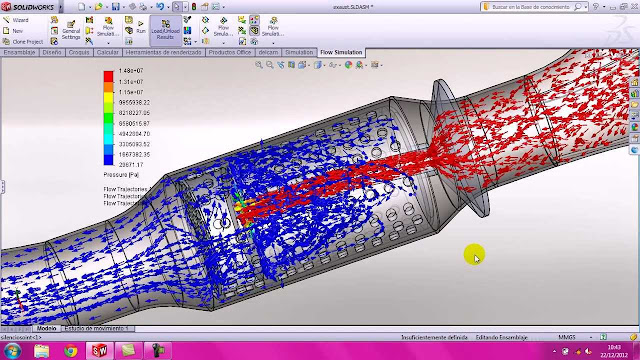
The design process of the exhaust
muffler should comprise a precise approximation of space essential for the
exhaust component, backpressure to engine, components weight, gas flow and
distributions, gas density and temperature distributions, the interaction of
the plenum with external surfaces around, and the thermal interaction of the
exhaust muffler with external surfaces through internal convection, conduction,
and radiation. CFD investigations of exhaust mufflers should take much
iteration time to converge, and study should not exclude complicated models
because the flow regimes comprise high subsonic compressible internal flow,
regions with high vortices and low velocity wake regions.

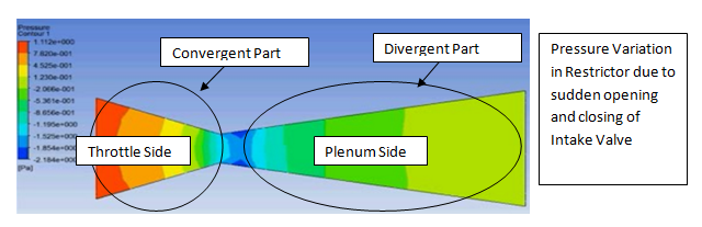
Exhaust manifold should be considered
for reducing the angle of bend pipes all through the exhaust gases path to
decrease the air friction. For initial study, few assumptions needs to be
considered such as flow of burning gases at a speed of 20 m/s and a temperature
of 300°C. The Flow and Pressure simulation should be done to study volumetric
efficiency and back pressure.

Simulation:
In above model exhaust silencer must be
added now. Assumption has been taken for end correction values as shown in next blog. Please read next blog for 1D simulation of Exhaust Silencer.