DFMEA of Intake Manifold
DFMEA is primary unavoidable and
essential step in designing process. All the possible failure modes related to
performance, design, material and manufacturing have been discussed in detail.
Also recommendation has been made to improve design process for each and every
failure. (RPN above 100 is very dangerous)
Function
|
Potential Failure
|
Failure Effect
|
SEVERITY
|
Potential Causes
|
OCCURANCE
|
Design Control Method
|
DETECTION
|
RPN
|
|
Prevention
|
Inspection
|
||||||||
Plenum
|
Flow
Chocking
|
Uneven
Torque Output
High
Intake Noise
|
7
|
Wrong
Plenum Location
Wrong
Plenum shape,
Wrong
Plenum Volume
|
5
|
Do many
iterations for different plenum shape and Volume for different air
temperature.
|
Engine
Dyno Test
|
2
|
10*5*2=
70 |
High Pressure
Waves
|
|||||||||
Back
Flow
|
|||||||||
Low
Charge Density
|
|||||||||
Uneven
Flow
|
|||||||||
Runner
|
Chocking
|
Low
Peak Torque ,
Peak
Torque at inaccurate RPM
|
8
|
Wrong
Runner Length
Wrong
Cross Section
|
4
|
Runner
Length & Cross Section Optimization
Iterations
for Throttle Bore.
Valve
timing to increase intake air and Internal EGR
|
Engine
Dyno Test
|
3
|
8*4*3
=96
|
Pressure
Wave
|
|||||||||
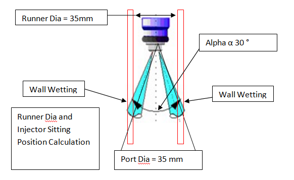
Wall
Wetting
|
Low
Fuel Efficiency
|
||||||||
Injection
Delay
|
|||||||||
High
Pumping Loss
|
Power
Loss
|
||||||||
Low
Volumetric Efficiency
|
|||||||||
Injector
Sitting Groove
|
Fuel
Leakage
|
Accident
/ Fire
|
10
|
Wrong O
Ring Dia, Wrong Material,
Wrong
Grove Size,
Wrong
Surface Roughness
|
8
|
Filling
Ratio & Compression Ratio Calculation and Simulation
|
High
Pressure Leakage Test on 100% Part
|
2
|
10*8*2
=160
|
Wrong
Axis
|
|||||||||
Injection
Delay
|
Power
Loss
Low
Fuel Efficiency
|
7
|
Distance
between Injector and Valve is Very Large or small.
Wrong
Injection Timing
|
3
|
Air
Fuel Mixing Simulation for different designs
|
Engine
Dyno Test
|
3
|
7*3*3
=63
|
|
Unmixed
Fuel
|
|||||||||
MAP
Sensor Functioning
|
Wrong Reading
|
Wrong
Air Fuel Ratio
|
4
|
Electromagnetic
Noise
No ECU
Compatibility
Wrong
Positioning of sensor
|
3
|
Do
Intake CFD to decide sensor location
|
Engine
Dyno Test
|
7
|
4*3*7=84
|
Variation
in Reading
|
2
|
4*3*2=24
|
|||||||
Air
Leakage
|
Wrong
Grove Size in In-Mani
|
Surface
Finish and O Ring Calculation
|
Engine
Endurance Test
|
||||||
Temperature
Sensor Functioning
|
Erroneous
Reading
|
Wrong
Air Fuel Ratio
|
4
|
Electromagnetic
Noise
No ECU
Compatibility
Wrong
Positioning of sensor
|
3
|
Do
Intake CFD to decide sensor location
|
Engine
Dyno Test
|
7
|
4*3*7=84
|
Variation
in Reading
|
2
|
4*3*2=24
|
|||||||
Gasket
|
Leakage
|
Accident
|
10
|
Wrong
thickness
Wrong
Mounting Hole Dia and Tolerances
Wrong
Material
|
2
|
Stress
and Strain CFD, Thermal Stress Simulation
|
Engine
Dyno Test
|
2
|
10*2*2=40
|
Burn
|
8*2*2=32
|
||||||||
Intake
Assembly on Cylinder Head
|
Air
Leakage
|
Low
Volumetric Efficiency
|
8
|
Wrong
Tolerance, Wrong Material,
Shrinkage
due to Thermal Expansion
|
2
|
GDNT
and Tolerance Stack up Analysis
|
Engine
Durability Test
|
2
|
8*2*2=32
|
Bolt
Hole Mismatch
|
|||||||||
Fatigue
and Crack
|
|||||||||
Rail
Assembly on Intake
|
Fuel
Leakage
|
Accident
Fire
|
10
|
Wrong
Tolerance, Wrong Material,
Shrinkage
due to Thermal Expansion
|
4
|
GDNT
and Tolerance Stack up Analysis
|
Engine
Durability Test
|
4
|
10*4*4=160
|
Bolt
Hole Mismatch
|
|||||||||
Fatigue
and Crack
|
|||||||||
Diffuser
Pipe Assembly on Intake
|
Air
Leakage
|
Low
Volumetric Efficiency
|
8
|
Wrong
Tolerance, Wrong Material,
Shrinkage
due to Thermal Expansion
|
2
|
GDNT
and Tolerance Stack up Analysis
|
Engine
Durability Test
|
2
|
8*2*2=32
|
Bolt
Hole Mismatch
|
|||||||||
Fatigue
and Crack
|
|||||||||
Based on above DFMEA following are some important recommendation for designing Intake Manifold :-
Function
|
Recommended Action
|
|
Plenum
|
Ensure Air cooling of
plenum.
Place air inlet at centre
of plenum.
Use Resonator or Silencer
|
|
Runner
|
Use Tapered design Runner,
Use Plastic if possible to
reduce wall temperature.
Have extra material on
intake and rail to machining, to fix injector axis to avoid wall wetting.
|
|
Injector Sitting Groove
|
Maintain high Surface
Finish at O Ring Grove,
Chamfer Grove to avoid O
Ring Cut
|
|
Do benchmarking of other
good engine to decide injector location.
|
||
MAP Sensor Functioning
|
Place MAP inside Plenum
where flow velocity is least.
|
|
Temperature Sensor Functioning
|
Sensing Element should be
in centre of cross section & where flow is maximum.
|
|
Gasket
|
Use Metal Gasket with high
surface finish. Have Minimum Hole and Position Tolerance.
|
|
Intake Assembly on Cylinder Head
|
Keep Engine Vibration Low.
Use High
Factor of safety for
Stress and Stain.
Keep gasket hole bigger
than hole in intake. Also Gasket Hole can be made Oval to move and fix
it.
|
|
Rail Assembly on Intake
|
||
Diffuser Pipe Assembly on Intake
|
||
Step 1 was Requirement Study
Step 2 is DFMEA as above
Next Step 3- Assembly of Fuel Injector on Intake Manifold plus Assembly of Fuel Delivery Rail on Intake Manifold - Next Nest Step Read next article.


